Cylinder embedded in another cylinder—smooth
← Previous: Thick cantilever cylinder | ↑ Index | Next: Cylinder embedded in another cylinder—rough →
| Title | Cylinder embedded in another cylinder—smooth |
| Tags | elasticity compression bending |
| Runnng time | a few seconds |
| See also | 115-cyl-cyl-rough |
| CAEplex case | https://caeplex.com/p/f7916 |
| Available in | HTML PDF ePub |
1 Problem description
Consider a vertical cylinder aligned with the z axis of radius r_1=25~\text{mm} and height h=50~\text{mm} which is embedded into another larger vertical cylinder of radius r_2=50~\text{mm} with the same height h. The base of the larger embedding cylinder lies on the x-y plane and the embedded cylinder is shifted h/2=25~\text{mm} upwards (fig. 1. The material properties are given in tbl. 1
| Young modulus E [GPa] | Poisson’s coefficient \nu | |
|---|---|---|
| Small cylinder (stem) | 120 | 0.26 |
| Large cylinder (base) | 2.5 | 0.36 |
The base and the lateral surface of the large cylinder are fully fixed. The upper surface of the stem has a traction condition \sigma_t = (+1,0,-10)~\text{MPa} so both compression and bending solicitations exist.
Figure 1: A small cylinder embedded into another one. CAD from CAEplex https://caeplex.com/p/f7916 (rotate and zoom it).
2 Geometry and mesh
The geometry was created in FreeCAD and exported as a BREP file. The following cyl-cyl-smooth.geo loads the geometry and defines the physical groups:
- volume
stemis the small cylinder, - volume
baseis the large cylinder, - surfaces
fixedare the base and the lateral surfaces of the large cylinder (base) which are to be fixed, and - surface
loadis the top surface of the small cylinder (stem).
Merge "cyl-cyl-freecad.brep";  // load geometry

// physical groups
Physical Volume("stem") = {1};
Physical Volume("base") = {2};
Physical Surface("fixed") = {5, 7};
Physical Surface("load") = {3};

// mesh options
Mesh.CharacteristicLengthMax = 3.0;

Mesh.SecondOrderLinear = 0;  // curved
Mesh.ElementOrder = 2;       // second-order elements

Mesh.Algorithm = 6;
Mesh.Algorithm3D = 1;

Mesh.Optimize = 1;
Mesh.OptimizeNetgen = 1;
Mesh.HighOrderOptimize = 1;
3 Input file
The annotated input file cyl-cyl-smooth.fin explains what it does. Properties in multi-material problems are given using the MATERIAL keyword.
MESH FILE_PATH cyl-cyl-smooth.msh DIMENSIONS 3    # load mesh

# assign per-material properties
MATERIAL stem E 120e3  nu 0.26
MATERIAL base E 2.5e3  nu 0.35

# set boundary conditions
PHYSICAL_ENTITY fixed BC fixed
PHYSICAL_ENTITY load  BC tx=1 tz=-10

# explicitly ask Fino to always smooth stresses and to flat-average stresses
FINO_SOLVER SMOOTH always ELEMENT_WEIGHT flat
FINO_STEP

# write output
MESH_POST FILE_PATH cyl-cyl-smooth-fino.vtk VECTOR u v w sigma

# report maximum diplacement in scientific notation
PRINT "Maximum displacement magnitude:" %e displ_max "mm"
4 Execution
Besides reporting the maximum displacement, which will be used when comparing results with CalculiX, a single VTK file cyl-cyl-smooth-fino.vtk with the displacement field and the von Mises stress distribution is created.
$ gmsh -v 0 -3 cyl-cyl-smooth.geo
$ fino cyl-cyl-smooth.fin
Maximum displacement magnitude: 2.542721e-02    mm
$
Note that we ask Fino to always smooth stresses, unlike Cylinder embedded in another cylinder—rough where we investigate what happens if stresses are never averaged.
5 Results
Figs. 2 (a), 2 (b) show the stresses over the warped geometry. As expected, both compression and bending is obtained. The “curved” tetrahedra (and triangles) can be seen, especially on the stem as each actual second-order triangle is shown as composed of four smaller ones which are not co-planar.
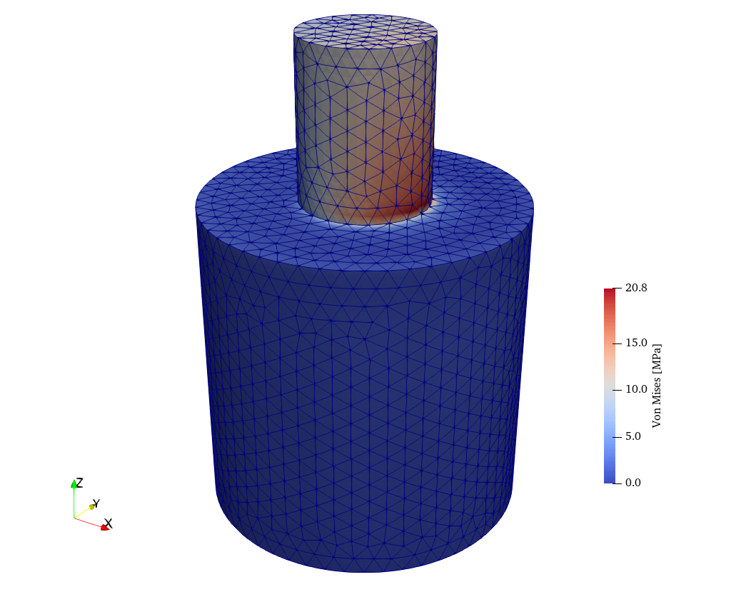
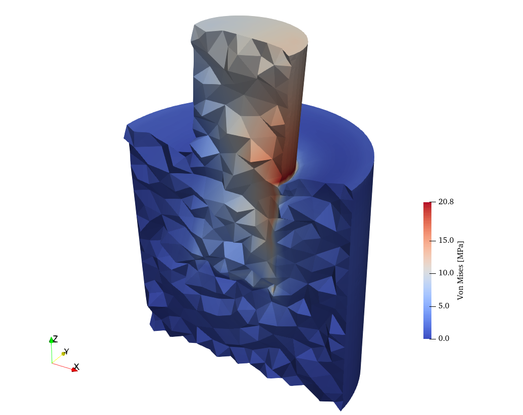
Figure 2: Von Mises stresses obtained by Fino. a — Full view, b — Clipped & warped \times 250 view
6 Check
The same problem is solved with CalculiX using an input file created with FreeCAD FEM module (this is the reason the original geometry was created with FreecAD) with the same Gmsh-generated mesh as when solving with Fino. CalculiX’ output FRD file and Fino’s output VTK file are both read back by Fino (actually by the wasora framework) and an algebraic difference is taken at each point of space in order to create a new VTK file comparing the two solutions:
# read Fino's results
MESH NAME fino FILE_PATH cyl-cyl-smooth-fino.vtk DIMENSIONS 3 {
  READ_SCALAR u_v_w1 as u
  READ_SCALAR u_v_w2 as v
  READ_SCALAR u_v_w3 as w
  READ_FUNCTION sigma
}

# read CalculiX' results
MESH NAME ccx FILE_PATH cyl-cyl-smooth.frd DIMENSIONS 3 {
 READ_FUNCTION D1  READ_FUNCTION D2  READ_FUNCTION D3
 READ_FUNCTION SXX READ_FUNCTION SYY READ_FUNCTION SZZ
 READ_FUNCTION SXY READ_FUNCTION SYZ READ_FUNCTION SZX
}

# compute Von Mises for ccx out of the stress tensor
SVM(x,y,z) := sqrt(0.5*((SXX(x,y,z)-SYY(x,y,z))^2 + \
                        (SYY(x,y,z)-SZZ(x,y,z))^2 + \
                        (SZZ(x,y,z)-SXX(x,y,z))^2 + \
                         6*(SXY(x,y,z)^2 + SYZ(x,y,z)^2 + SZX(x,y,z)^2)))

# compute algebraic differences
diff_sigma(x,y,z) := SVM(x,y,z) - sigma(x,y,z)
diff_u(x,y,z) := D1(x,y,z) - u(x,y,z)
diff_v(x,y,z) := D2(x,y,z) - v(x,y,z)
diff_w(x,y,z) := D3(x,y,z) - w(x,y,z)

# write VTK files using both grids to make sure they are the same
MESH_POST MESH fino   FILE_PATH diff-smooth-fino.vtk  VECTOR diff_u diff_v diff_w diff_sigma
MESH_POST MESH ccx    FILE_PATH diff-smooth-ccx.vtk   VECTOR diff_u diff_v diff_w diff_sigma
Fig. 3 (a) shows the results of the abolute differences in displacements as computed by Fino and CalculiX. The maximum magnitude is 1.4 \times 10^{-4}~\text{mm} whereas the maximum computed displacement, as reported in the terminal mimic, is 2.5 \times 10^{-2}~\text{mm}—although these maxima do not occur at the same locations. On the other hand, it can be seen in fig. 3 (b) that the maximum differences in stresses are in the order of 0.3%.
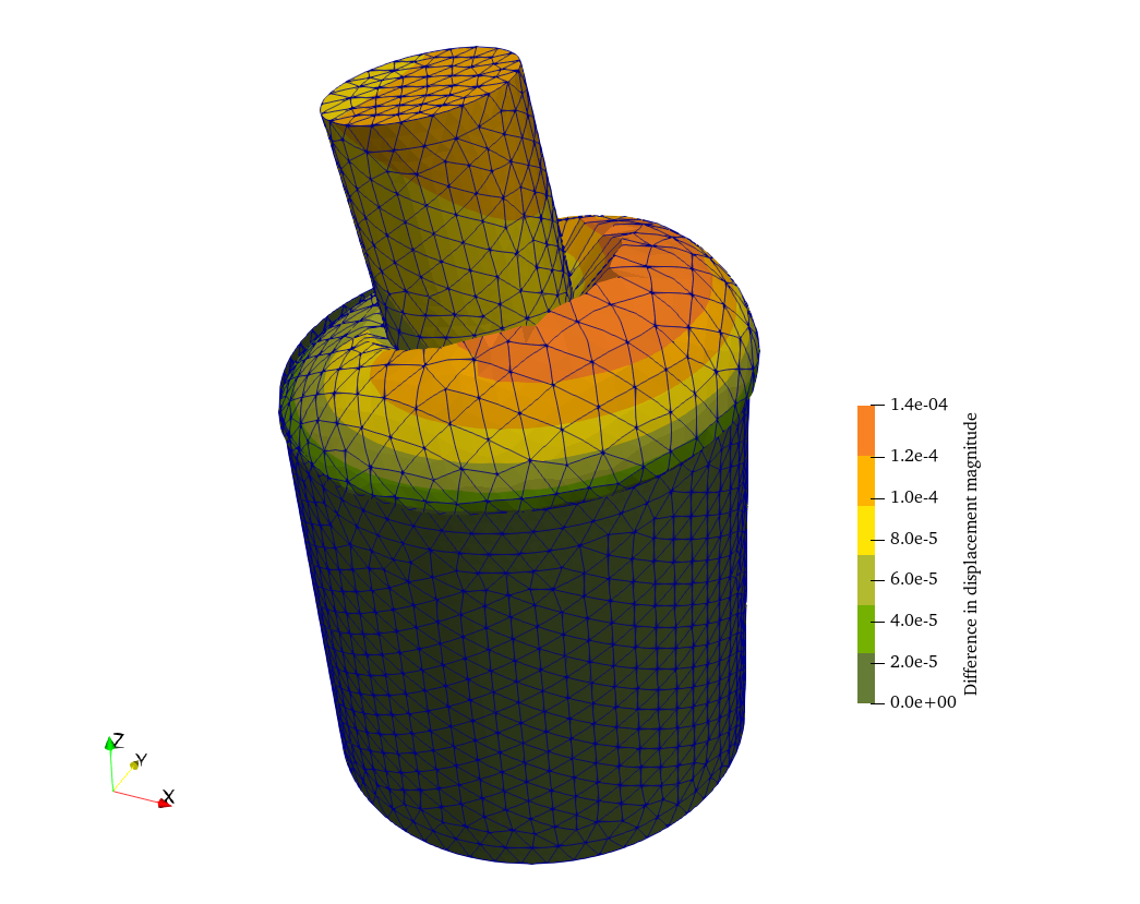
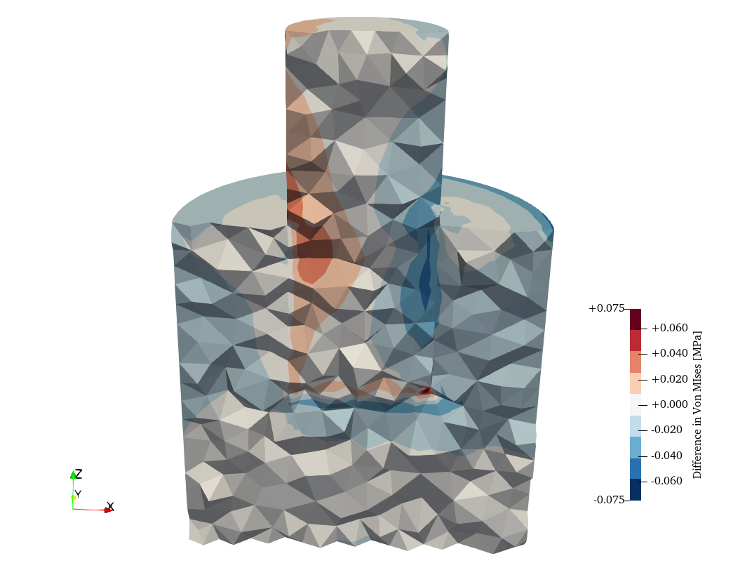
Figure 3: Absolute differences between Fino and CalculiX. a — Displacements warped \times 10^5 with the difference, b — Stresses warped \times 250 with the original displacements